Friday, November 29, 2013

14.318 Mhz CW Direct Conversion Receiver


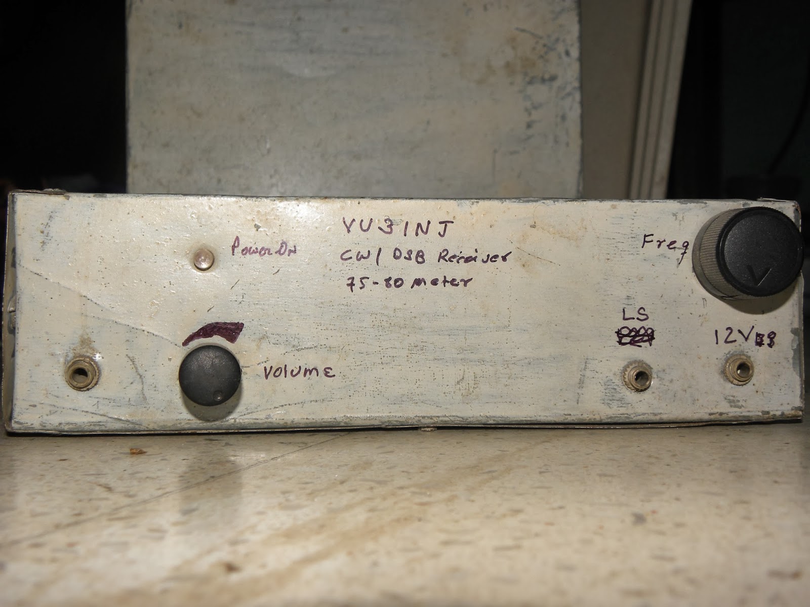
This receiver is made for the testing the CW xtal transmitter (14.318 Mhz )as shown in othe previous posts.
 
Ckt is similar to the 4.000 Mhz, 75meter rx. but, this time i have put the much needed front end gain block the RF pre-amp taken from PA2OHH.

First main goal of this receiver was to be extremely portable, small antenna, powered  by 9v pp3 dry batery, less tuning. With the diode dbm  it was not possible to meet all these criteria, to find an alternative went for this design. It lakes the audio filter, but for occasional and portable operations it is tolerable.

IC ta7358ap is used as front end. It saved me lots of trouble of making seperate  vfo, buffer and product detector. After all I am using the single frequency.

One stage of audio pre-amplifier (bc547 or bc108) and standard LM386 is used to drive the speaker. It gives loud signal. You can use headphone also.
 
LM7805 is used, instead of zener diode. It looks little overkill, but  gives good voltage regulation and once installed i dont have to worry about it.

Rf preamp is taken from PA2OHH website, i chose this to find out alterntive of the  cascode rf pre-amp of rm96 .... its performance and end result will take some time, please wait.....

whole ckt and details will follow. de vu3inj

NB as of 7 Dec 2013  Receiver Front End is okey and working. It needs to be peaked/tweaked for max signal, i will run a small vfo on portable battery , take it to some distance(3km) and see how well (DCR 14318 ) resolves the microvolt level signals.

11 Dec 2013  I was  queried by a friend regarding the design. It has been not declared finished as some components values and parts are being changed to get more performance and improvements please wait.....

17 Dec 2013
The friend once again ringed me up. The gist of our convesation......

At low freq may  be a single tuned ckt will work but higher we go, we needs to put more tuned ckt in the front end as the DC receives are very wide band and there is no selectivity except the filtes. gain of receiver is good but there is AM radio signal coming into the dc receiver. which is the problem of every high gain receiver poorly designed and poorly constructed. ..... if you make the input band pass filter with the ferrite slug cores it will be easy to tune. use 30 swg, 30 turns with 33 pf on alladin former (or use a piece of sketch pen with siug ). Couple the top of these tuned ckt with 2.2 pf capacitors.

Please don't reach to the conclusion that ckt does not perform as i have not finished it fully. it needs few tweaking / experimentatations. as front end is not giving performance that i wanted.

I am using this rx to monitor my tx signal. i am also making another similar ckt for second 20 meter tx within this week my result for this rx will be told and uploaded. i have to upload the write-ups for it. dont worry i will not let u down.

I made a two three changes in the ckt to reduce motor boating, hum etc but still there is  AM breakthrough when coupled with big dipole. antenna With short 1 meter antenna rx works very good for monitoring my own local cw signals ! Actually this was the purpose it was designed for...... It never was a stand alone complete receiver. 
At  this time it stays as it is and will further improvise with some good front end filter and tell the result later on as now working on the transmitter projects .....

I am still working on this thing. If you find this interesting and tempted to build please look also http://vu3inj.blogspot.in/2014/01/tuning-up-dc-rx.html

(I have opened the box for some improvements..... Jan2015)

Thursday, November 21, 2013

14.318 Mhz. CW, 20 meter transmitter

14318kc transmitter:-


bitx version-1 (by vu2ese) linear
This is a 20 meter transmitter brewing up after long 10 years of absence in homebrew. So, the technique is of old faithful transistors ( he he ! in the age of digital the transistors are also old tech !)

Here cheaply available (rs.15) fundamental Xtal is used. 14.318 Mhz which falls on the one end of the ham band. But, generally hams does not go that much high up ! so, with this tx sked is needed. And one possible benefit will be there will be less QRM of QRO rigs. around 14.200kc band is crowded.

1. First board:- Xtal osc with buffer. This ckt is standard. Here 1k pot is used to control the RF going into the RF amp chain.

2. Second Board:- This is the single stage tuned amp. I have used the BF494 but any c series transistor can be used. If it does not work nice will change it to 2n2222 in metal pack. Here, old alladin former is used as tank of tuned amp. This is 10 years old legacy.

3. This board consist of driver amp based on 2n2218 and RF power amp based on IRF510. This is very straight and standard amplifier. Heat sink is must for IRF.  Output filter is not designed at present. Once it heats up dummy load filter will be made and connected to the dipole. I am expecting power of about 5w.

CW TX


Only part tested is upto driver amp. I am thinking of making the RF power stage on the basis of VU2ESE, OM farhans bitx20 v1 (first version using the tap-washer !)  i.e air core transformer. But, vu2*** informs about different version of this output transformer . So, will try his suggestions also. And see which thing works for me. Only thing important is working ckt. I am ready to borrow from any idea, but it must work me.

NB:-At present (nov2013) this project is not complete. I want to power finale amp from 18vdc to increase power,so it will need few more changes.  ( I did power up with 24volt  got around 3-4watt, disliked using  two different voltages for single transmitter thus ended up using 12volt and 2watt ok.)

As of 28 Jan 2015 I did not drive the exciter with 18/24 on the final irf510 instead accepted whatever power it produced with 12vdc and drive it to external linear. This big linear produces around 20watt and punching whole indian continents.

Will upload the finished fotos. soon....

As of 14 feb 2015 made replica of this transmitter. It works. People are making the transmitters for this freq. It will become popular one day. de vu3inj, indrajitsinh.

WHEEL HAS BEEN RE-INVENTED, USE IT

Wednesday, November 13, 2013

Direct Conversion Receiver

direct conversion receiver

80 meter oscillator & buffer

dc receiver front view


This is the working direct conversion receiver. I am using along with 80 meter xtal transmitter for test purpose. Initially it was made to test whether Diode Product Detector could be used or not. I was skeptical about diodes product detector but ultimately i beleived in these diodes.


It contains four stages.
1.   LO with buffer to drive the diodes. which requires 7dm power.
2.   Product detector of Four diodes, as shown in previous post.
3.   Active AF Filter, this is also shown in some post in this blog.
4.   Standard LM386 af amplifier.

All stages are operated from 12 Dc regulated voltage.It needs antenna (dipole)  and BPF at front end.

For 20 meter some sort of Rf pre-amp is a must. I had used the Cascoded RF amp with filter. LO was same but one stage of Transistor multiplier amplifier was used to drive the dbm. That was my best receiver to operate. I used it extensively  during the y2k as valves receiver required more power consumptions and this was just a small size receiver.

In the front panel, on left corner there is unmarked socket it gives the output directly from filter so that it can drive external AF amplifier.

Enjoy the simplicity.
***************************************************************
Here is the circuit.

 The block diagram. This is the typical diagram. All the direct conversion receiver follows this stages.

Product detector. This is standard circuit. I was making the receiver and little skeptical of passive diodes. For the sack of go or nogo test connected the diode dbm and presto it worked first time. It lacked the audio so i put the resistor as shown and it became my favourite. It is given in the QRP Notebook also.

How to wind the core ? Make a trifiliar wire. Three wire is taken and twisted for 5 to 8 turns per inch by handdrill. then wound the 15 to 17 turns. One side wire end are labelled as 1,2,3 and their other ends are labelled as a, b,c. Test for dc continuity. 1-a,2-b,3-c and no other pair should show the zero. If it shows then wire enamel is broken and it needs to be rewound using new wire. Connect 2and a and your transformer is wound ok. Becareful with scrapping the enamel.

to be continue......


Tuesday, November 12, 2013

Diode Product Detector

Diode product detector. 4 diodes used are matched 1N4148. How to match ? using the dc resistance in DMM (digital multimeter). Try a dozen resistor. Measure and write down their resistance. Now choose 4 with closest resistance.

Balun core or any RF toroid can be used.

SWG 30 wire 3 strands twisted.


Both transformers are identical. Resistor is used to take the AF and audio is given to AF Filter..
product detector
Product detector. This is standard circuit. I was making the receiver and for the sack of go or nogo test connected the diode dbm and presto it worked first time. It lacked the audio so i put the resistor as shown and it became my favourite. It is given in the QRP Notebook also.


tifiliar transformer
How to wind the core ? Make a trifiliar wire. Three wire is taken and twisted for 5 to 8 turns per inch by handdrill. then wound the 15 to 17 turns. One side wire end are labelled as 1,2,3 and their other ends are labelled as a, b,c. Test for dc continuity. 1-a,2-b,3-c and no other pair should show the zero. If it shows then wire enamel is broken and it needs to be rewound using new wire. Connect 2and a and your transformer is wound ok. Becareful with scrapping the enamel.

Saturday, November 9, 2013

PRE MIXED OSCILLATOR, 7059 Khz


This is the ckt for the premixed oscillator which i used for the xtal controll for VWN CW transmitter. I just wanted to test that a stable mixer can be realized with TA7358ap or not. Fortunately it gives very good result. Filter is one stage tuned amp and another tank.

Osc ckts are similar except the crystal and its tuning pf. Adjust preset for best mixing quality. Signal should be clean.

BPF tanks were pre-tuned in the osc , freq meter stage shown in previous posts. IT was observed there was no need of retuning. but i picked it for little better signal output.

Friday, November 8, 2013

A Lion and pigs story

This sculpter has a very unique story of bravery like a lion and cunningness of pig. If you knew the story it , you will be sure able to see both the pig and lions. Considering it as a metaphore , in your surrounding and in your life experience you might have heard also of the treachury and unique way of taking revenge.

Thursday, November 7, 2013

AF Filter


This is an AF pre-amp and filter amplifier.  First stage BC547b is used as low noise af amplifier( here BC109c, in metalic pack gives good result). Second stage contains the OP AMP based filter with little gain. Third stage is also similar. From this AF is given to the standard LM386 amp which gives us comfortable audio.(this 386 amp is not shown here).

I used general purpose OP-AMP ic LM741 but when LF411 was used in first OP Amp stage it gave better performance then 741. At this ckt lower noise components helps tremendously.

This stages are powered from 12v DC , a well regulated sourse is must. there are few components on back side also.

It gives good Audio response. This is my favourite and reproduceable ckt block.

40 meter QRP transmitter

 
This is my first working DSB modulator. It uses two TA7358AP ic as modulator and mixer. Audio ic LM741 is used as af amp.

LM7805 voltage regulator used. 2N2222a is used as tuned RF amplifier that reduces the spurious mixer products and gives the clean signal.

After sometime some fault appeared with veroboard and it went blank. So the project of going DSB over 40 meter was stopped as there was no compatible receiver for it.

(But, however this again reborn in Jan2015 ad 14195kc dsb exciter. )