Thursday, December 26, 2013

DSB Transmitter, Xtal 14318kc

DSB 14318KC QRP TRANSMITTER
After successful assembling first CW tx based on 14318kc fundamental xtal my faith grew on the ckts. Then a friend after initial testing told me there is tone ! that means there will be few taker of CW tx. Make a fone tx and test it.

I am brewing it. Parts are all standard.

For AF amp LM741 is used. TA7358AP ic does the work of osc and dsb modulator.

Then these stages are followed by three stage amp. One tuned amp. broad band driver amp based on 2n2218 and last single ended RF PA based on IRF510.

I am testing it and if my ham / friends from (100km my nearest hams) tells me critical report 54 then i will be cofident to announce that it is a boy !

I am not sure whether this little tx can span more than that... but who knows this might put me on air ! If it works i will consider it a xmus miracle.... vu3inj
29 dec 2013. My ham friends were looking for me as a sked was announced but they could not find me due to mismatch and low power at my end. On dummy load it gives a good audio and good power but problem is with antenna working on it. Please friends do visit me... i plan to work on air with this tx in new year and daily after 10pm in the night. all are welcome....

NB:_ As of 2jan 2014 working on resovling the power issue. Solved it maybe it is comfortably providing about 700ma at 12 on 4 watt dummy load , 50 ohm. It becomes warm on just calling cq cq cq de vu3inj....... so i need some sort of tuner..... brewing the atu..... without atu antenna is not loading.

As of 11 Jan 2014, power increased but ATU needs to be brewed and confirmed SWL report from my nearest hams 100km far is awaited then will finally say pass or fail.and publish all write-ups.

As of 14 Jan 2014 a self oscillations in tuned stage was detected. This stage was looking innocent but there was no emmiter degenerations ( 0.1 mfd + 100 ohm resistor ! ) and on 24 volts power supply heating up of the final RF amp coil was noticed. However , there was no self oscillations. So, these things needs to be cured.....
As of 16 jan 2014.
cured by changing the tuned amp stage. but power went down. i also did put 100k plus 0.1mfd in gate to drain feedback, which reduced the distortion and also power. so, by feedback you can reduce the distortion, increase linearity with the penalty of the reduced power .
checked the field stregth with newly brewed rf detector. it explains why nobody answered my call pa need to give more power or external pa is needed. that it falks, dsb projects rd ends here.
Modules as used in the transmitter.

AF amplifier and DSB modulator


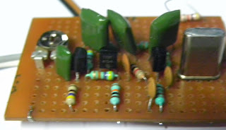
Here, ic TA7358AP used as balanced modulator. This 9 pin SIL ic is originally used in the front end of FM radio, so widely available and can do almost all the work of hard to find IC NE602, NE612 etc. internal oscillator is used between pin 6 and pin 7. a xtal of 14318kc is put with 33pf so it gives me the frequency of 14313kc. output from pin 6 is followed by a emitter follower. from this stage modulated rf is given to the buffer amplifier. in cw tx this buffer is also used. after emitter follower stage one 1k resistor is put to reduce the rf going to buffer stage.
this is the over all layout as shown in the fotograph above. placement is shown on the test bed.


buffer amplifier stage

buffer amplifier is standard, R1-10K,R2-47K,R3-470ohm, R4-4K7, C1,C2 are by pass capacitor 0.1mfd.R6-100 ohm , vcc used is keyed 12 dc, q1 is BF194 or BF494, Q2 is BC547b . A 10 preset is used to regulate the drive level going to the tuned amplifier. i put it for maximum to the point where it does not produce the distortions. earlier when another type of tuned stage was used this there was distortion. also there should be a 0.1mfd capacitor between the preset and r3.

5volt dc regulated.
here 1n4007 diode is put to protect from wrong connections. c1-10mfd,c2-0.1mfd,c3-100mfd, electrolytic capacitors need be working voltage 50vdc and more. r1-4k7 and LED to see there is light. There is similar 12 volt module for giving the voltage to ptt stage. 


PTT STAGE
I had one old carbon mic from russian origin. so put it in a small box a small press to on switch was also installed. and that became PTT switch not shown in the ckt but it is there and connected between point 2 and point three. r1-1k, r2-4k7,q1- any pnp transitor here BC557 is used. relay is of 12 volt use whatever you find. diode accross is a 1n4007 please do put it correctly. Now a days i dont find the relay with more than two switched connections. So, you can paralled for switching pa stage also. i have left the pa stage vcc always connected.
RF INDICATOR

Tuned Amplifier
out of three stage of rf amp chain . first is the tuned amplifier. all the selectivity is here. this is the only tuned stage. for spectral purity there should be more tuned stage but as it increases the complexity and this stage give input to the driver stage.


Driver and Final PA stage
Then a driver stage based on 2N2218 and final amplifier stage based on the IRF510 was brewed main constraint was that i did not have the suitable ferrite material for the power amp, only toroid available was the balun core one piece and few toroidal core from CFL tube-this dont work beyound the 10 mhz, so this was a very serious problem, then i saw the farhans first bitx using the air core coils on plastic washers.  i could not find the suitable washers but 2cm plastic waterpipe was available and a very standard thing which can be available for some time.

As, this was experimental transmitter all the play with the settings, bias, components were done, it was abused so much that each day change was made and seen how it performed.


This is the same thing given in farhans bitx 1 version and also found in many other designs. there is not so much scope of any innovations or problem. Use it.


After the power amplifier  one stage LPF was put and then dummy load of 50 ohm  (or dipole antenna).

One point in time it tuned up very nicely. So, i published for sked, but aftersome time there was some problem in curing that power went to down, at first i did not realize that thing,then tested again and still problem needs to be rectified.
**********************************************************************
LETTER OF THANKS
Lots of friends, VU3HMM, VU3HML, OM S Kamble, VU3YFD, VU2KD, OM gurudatta and others tried to listen and help in improving, even OM VU2ESE also suggested one or two things.  OM Sandeep Lohias actively supported with his expertize & experience. From delhi VU2ATN, VU2YK,VU2RAK also gave positive feedbacks, but,  anyway this ckt did not stand to the point but gave a very valuable lessons and stirred lots of interest. VU2TOO also gave me moral support and VU2UPX was also closely watching and lots.

At this point in time this phase is over, will try it some other time with success.I will try to write-up fully within short time, as busy in new mqth,

Thanks you friends.... vu3inj, indrajit 17 jan 2014

thats it folk wheel will be re-invented soon !

Jan 2015 problem found. Power is low about 2watt also antenna was not on high building. With input from VU2KD & VU2DEV antenna was raised high, linear was loaded and it worked very well......


this works


Sunday, December 22, 2013

untuned radio

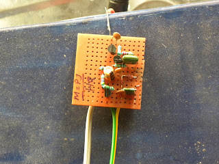
You will be surprized, i dont have a simple single general coverage radio receiver to receive shortwave or local AM stations. I have communications receivers only (few homebrew cw and dsb and two boat anchors) and . During designing of the Direct Conversion receiver there was lots of am breakthrough.... this led me to try out an idea.

Years ago i had made it with germanium diodes OA79, OA32 ( forgetting the names ... ). Now we have only silicon diodes freely available. So putting an amp in the front.

Long antenna, RF amp, Diode detector for AM signal. AF pre-amp, AF Amplifier.... and thats all.

With two transistors BF194b a cascoded wide-band RF amp is made. Then a diode detector is made with two 1N4148 to decode AM signals. BC 547 works as AF pre-amp then rest of work is done by Standalone Amplifier box ( which contains 12v dc power and LM386 based amplifier and small speaker). I listen whatever stations comes in. There is no tuned ckt.

It requires a really long single wire antenna say more than 20 meter high strung on air. My 20 meter dipole did not work for it.

It gives me company by making noices, stations comes and goes what a wonderful pleasure......

Friday, November 29, 2013

14.318 Mhz CW Direct Conversion Receiver


This receiver is made for the testing the CW xtal transmitter (14.318 Mhz )as shown in othe previous posts.
 
Ckt is similar to the 4.000 Mhz, 75meter rx. but, this time i have put the much needed front end gain block the RF pre-amp taken from PA2OHH.

First main goal of this receiver was to be extremely portable, small antenna, powered  by 9v pp3 dry batery, less tuning. With the diode dbm  it was not possible to meet all these criteria, to find an alternative went for this design. It lakes the audio filter, but for occasional and portable operations it is tolerable.

IC ta7358ap is used as front end. It saved me lots of trouble of making seperate  vfo, buffer and product detector. After all I am using the single frequency.

One stage of audio pre-amplifier (bc547 or bc108) and standard LM386 is used to drive the speaker. It gives loud signal. You can use headphone also.
 
LM7805 is used, instead of zener diode. It looks little overkill, but  gives good voltage regulation and once installed i dont have to worry about it.

Rf preamp is taken from PA2OHH website, i chose this to find out alterntive of the  cascode rf pre-amp of rm96 .... its performance and end result will take some time, please wait.....

whole ckt and details will follow. de vu3inj

NB as of 7 Dec 2013  Receiver Front End is okey and working. It needs to be peaked/tweaked for max signal, i will run a small vfo on portable battery , take it to some distance(3km) and see how well (DCR 14318 ) resolves the microvolt level signals.

11 Dec 2013  I was  queried by a friend regarding the design. It has been not declared finished as some components values and parts are being changed to get more performance and improvements please wait.....

17 Dec 2013
The friend once again ringed me up. The gist of our convesation......

At low freq may  be a single tuned ckt will work but higher we go, we needs to put more tuned ckt in the front end as the DC receives are very wide band and there is no selectivity except the filtes. gain of receiver is good but there is AM radio signal coming into the dc receiver. which is the problem of every high gain receiver poorly designed and poorly constructed. ..... if you make the input band pass filter with the ferrite slug cores it will be easy to tune. use 30 swg, 30 turns with 33 pf on alladin former (or use a piece of sketch pen with siug ). Couple the top of these tuned ckt with 2.2 pf capacitors.

Please don't reach to the conclusion that ckt does not perform as i have not finished it fully. it needs few tweaking / experimentatations. as front end is not giving performance that i wanted.

I am using this rx to monitor my tx signal. i am also making another similar ckt for second 20 meter tx within this week my result for this rx will be told and uploaded. i have to upload the write-ups for it. dont worry i will not let u down.

I made a two three changes in the ckt to reduce motor boating, hum etc but still there is  AM breakthrough when coupled with big dipole. antenna With short 1 meter antenna rx works very good for monitoring my own local cw signals ! Actually this was the purpose it was designed for...... It never was a stand alone complete receiver. 
At  this time it stays as it is and will further improvise with some good front end filter and tell the result later on as now working on the transmitter projects .....

I am still working on this thing. If you find this interesting and tempted to build please look also http://vu3inj.blogspot.in/2014/01/tuning-up-dc-rx.html

(I have opened the box for some improvements..... Jan2015)

Thursday, November 21, 2013

14.318 Mhz. CW, 20 meter transmitter

14318kc transmitter:-


bitx version-1 (by vu2ese) linear
This is a 20 meter transmitter brewing up after long 10 years of absence in homebrew. So, the technique is of old faithful transistors ( he he ! in the age of digital the transistors are also old tech !)

Here cheaply available (rs.15) fundamental Xtal is used. 14.318 Mhz which falls on the one end of the ham band. But, generally hams does not go that much high up ! so, with this tx sked is needed. And one possible benefit will be there will be less QRM of QRO rigs. around 14.200kc band is crowded.

1. First board:- Xtal osc with buffer. This ckt is standard. Here 1k pot is used to control the RF going into the RF amp chain.

2. Second Board:- This is the single stage tuned amp. I have used the BF494 but any c series transistor can be used. If it does not work nice will change it to 2n2222 in metal pack. Here, old alladin former is used as tank of tuned amp. This is 10 years old legacy.

3. This board consist of driver amp based on 2n2218 and RF power amp based on IRF510. This is very straight and standard amplifier. Heat sink is must for IRF.  Output filter is not designed at present. Once it heats up dummy load filter will be made and connected to the dipole. I am expecting power of about 5w.

CW TX


Only part tested is upto driver amp. I am thinking of making the RF power stage on the basis of VU2ESE, OM farhans bitx20 v1 (first version using the tap-washer !)  i.e air core transformer. But, vu2*** informs about different version of this output transformer . So, will try his suggestions also. And see which thing works for me. Only thing important is working ckt. I am ready to borrow from any idea, but it must work me.

NB:-At present (nov2013) this project is not complete. I want to power finale amp from 18vdc to increase power,so it will need few more changes.  ( I did power up with 24volt  got around 3-4watt, disliked using  two different voltages for single transmitter thus ended up using 12volt and 2watt ok.)

As of 28 Jan 2015 I did not drive the exciter with 18/24 on the final irf510 instead accepted whatever power it produced with 12vdc and drive it to external linear. This big linear produces around 20watt and punching whole indian continents.

Will upload the finished fotos. soon....

As of 14 feb 2015 made replica of this transmitter. It works. People are making the transmitters for this freq. It will become popular one day. de vu3inj, indrajitsinh.

WHEEL HAS BEEN RE-INVENTED, USE IT

Wednesday, November 13, 2013

Direct Conversion Receiver

direct conversion receiver

80 meter oscillator & buffer

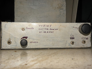
dc receiver front view


This is the working direct conversion receiver. I am using along with 80 meter xtal transmitter for test purpose. Initially it was made to test whether Diode Product Detector could be used or not. I was skeptical about diodes product detector but ultimately i beleived in these diodes.


It contains four stages.
1.   LO with buffer to drive the diodes. which requires 7dm power.
2.   Product detector of Four diodes, as shown in previous post.
3.   Active AF Filter, this is also shown in some post in this blog.
4.   Standard LM386 af amplifier.

All stages are operated from 12 Dc regulated voltage.It needs antenna (dipole)  and BPF at front end.

For 20 meter some sort of Rf pre-amp is a must. I had used the Cascoded RF amp with filter. LO was same but one stage of Transistor multiplier amplifier was used to drive the dbm. That was my best receiver to operate. I used it extensively  during the y2k as valves receiver required more power consumptions and this was just a small size receiver.

In the front panel, on left corner there is unmarked socket it gives the output directly from filter so that it can drive external AF amplifier.

Enjoy the simplicity.
***************************************************************
Here is the circuit.

 The block diagram. This is the typical diagram. All the direct conversion receiver follows this stages.

Product detector. This is standard circuit. I was making the receiver and little skeptical of passive diodes. For the sack of go or nogo test connected the diode dbm and presto it worked first time. It lacked the audio so i put the resistor as shown and it became my favourite. It is given in the QRP Notebook also.

How to wind the core ? Make a trifiliar wire. Three wire is taken and twisted for 5 to 8 turns per inch by handdrill. then wound the 15 to 17 turns. One side wire end are labelled as 1,2,3 and their other ends are labelled as a, b,c. Test for dc continuity. 1-a,2-b,3-c and no other pair should show the zero. If it shows then wire enamel is broken and it needs to be rewound using new wire. Connect 2and a and your transformer is wound ok. Becareful with scrapping the enamel.

to be continue......


Tuesday, November 12, 2013

Diode Product Detector

Diode product detector. 4 diodes used are matched 1N4148. How to match ? using the dc resistance in DMM (digital multimeter). Try a dozen resistor. Measure and write down their resistance. Now choose 4 with closest resistance.

Balun core or any RF toroid can be used.

SWG 30 wire 3 strands twisted.


Both transformers are identical. Resistor is used to take the AF and audio is given to AF Filter..
product detector
Product detector. This is standard circuit. I was making the receiver and for the sack of go or nogo test connected the diode dbm and presto it worked first time. It lacked the audio so i put the resistor as shown and it became my favourite. It is given in the QRP Notebook also.


tifiliar transformer
How to wind the core ? Make a trifiliar wire. Three wire is taken and twisted for 5 to 8 turns per inch by handdrill. then wound the 15 to 17 turns. One side wire end are labelled as 1,2,3 and their other ends are labelled as a, b,c. Test for dc continuity. 1-a,2-b,3-c and no other pair should show the zero. If it shows then wire enamel is broken and it needs to be rewound using new wire. Connect 2and a and your transformer is wound ok. Becareful with scrapping the enamel.

Saturday, November 9, 2013

PRE MIXED OSCILLATOR, 7059 Khz


This is the ckt for the premixed oscillator which i used for the xtal controll for VWN CW transmitter. I just wanted to test that a stable mixer can be realized with TA7358ap or not. Fortunately it gives very good result. Filter is one stage tuned amp and another tank.

Osc ckts are similar except the crystal and its tuning pf. Adjust preset for best mixing quality. Signal should be clean.

BPF tanks were pre-tuned in the osc , freq meter stage shown in previous posts. IT was observed there was no need of retuning. but i picked it for little better signal output.

Friday, November 8, 2013

A Lion and pigs story

This sculpter has a very unique story of bravery like a lion and cunningness of pig. If you knew the story it , you will be sure able to see both the pig and lions. Considering it as a metaphore , in your surrounding and in your life experience you might have heard also of the treachury and unique way of taking revenge.

Thursday, November 7, 2013

AF Filter


This is an AF pre-amp and filter amplifier.  First stage BC547b is used as low noise af amplifier( here BC109c, in metalic pack gives good result). Second stage contains the OP AMP based filter with little gain. Third stage is also similar. From this AF is given to the standard LM386 amp which gives us comfortable audio.(this 386 amp is not shown here).

I used general purpose OP-AMP ic LM741 but when LF411 was used in first OP Amp stage it gave better performance then 741. At this ckt lower noise components helps tremendously.

This stages are powered from 12v DC , a well regulated sourse is must. there are few components on back side also.

It gives good Audio response. This is my favourite and reproduceable ckt block.

40 meter QRP transmitter

 
This is my first working DSB modulator. It uses two TA7358AP ic as modulator and mixer. Audio ic LM741 is used as af amp.

LM7805 voltage regulator used. 2N2222a is used as tuned RF amplifier that reduces the spurious mixer products and gives the clean signal.

After sometime some fault appeared with veroboard and it went blank. So the project of going DSB over 40 meter was stopped as there was no compatible receiver for it.

(But, however this again reborn in Jan2015 ad 14195kc dsb exciter. )

Friday, October 18, 2013

DDS VFO by VU2UPX, J1 and J2 connectors

Description: 16mm Plastic Shaft Rotary Encoder with 10mA Maximum Operating Current for Welding Machine


Hi

Just to point out how you need to connect the Rotary Encoder and the 2 switches to make your DDS frequency synth to work

The Rotary encoder connects at J1 connector marked on the PCB. Pin#1 of J1 connects to GND and Pin#4 of the same connector connects to VCC (+5V). Pin#2/3 connect to the data pins.

In the figure shown below the Centre Pin is the GND/Common Pin and the other two pins go to the Data pin on the PCB. These type of connectors also have a inbuilt Push/Press switch, but right now we are not taking that into account , in our project.

So you can simply consider that the centre pin is #2 and the other two pins are 1/3.


This is the schematic Diagram of the Rotary Encoder + switch and the Pull-up resistors connected to the Data pins. As you can see that the Centre pin #2 is connected to GND (Pin@1/J1) and Pin#1/3 Connected to data pins , Pin#2/3 on J1. Vcc is obviously connected to the combined junction of the two pull-up resistors shown in the schematic diagram. The Back side two switch points are left NC (Not Connected).

There are two more switches that need to be connected to the project at J2 and the same philosophy applies. Pin#1@J2 is GND and Pin#4@J2 is VCC (+5V). Pin#2/3@J2 are the datapins which connect to the Switch with Pull ups.


These switches are used to jump between Frequency step size. Experiment to find out how this functions.

In short you will have to assemble these things separately on a vero board. My friend Ravi has assembled this thing on a Vero Board and maybe he can support my explanation with some photographs (Top/Bottom).

Hope you are now able to understand how to get the kit to work and hope to see your successful experimentation on the Blog.
 Regards
Charudatt

Please Note:-
It is explained very thoroughly, i can not think of writing it more beautifully, so am reproducing the mail as it is.Thanks, De vu3inj, indrajitsinh
Those who require PCB and programmed PIC please contact Ravi Miranda https://www.facebook.com/groups/Indian.Homebrewers/

Thursday, October 17, 2013

DDS VFO by VU2UPX


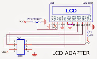
The circuit is in three parts. One is DDS Controller board consisting of the AD9850 and PIC.Second board consist of LCD display 16*2 , I have used chines JHD 162A. Third part is the Rotary Encoder and Swithes and the Flexible ribbon connector between the two modules.

A little story of mine.:- I had bought two DDS AD9850 modules from ebay (Om Priyashlok Arya). Then i was searching for the controller. Tried few known sources. But, there was some sort of problems like the genunie PIC was not available ,There was problem in programming. Another ham did not respond to my request. I had tried all the known sources. Some said you have to wait
 The DDS VFO
This is the original design by the VU2UPX himself. On my recent visit to the mumbai by chance i met the vu2upx and he promised to help, gave me PCB and programmed IC.  It turned out that his design approch was very different and genuine so that i could not search/find the ckt on google. Finally i gave up and sought his help in making this DDS VFO. I am in process of finally running and will update the information ASAP.

My request:- vu2upx is a very busy person. Friendsplease, if you have any query , questions please put it on facebook group and usually he responds within one or two days. thanks.

Tuesday, October 8, 2013

TA7358AP

I have fallen in love with this IC. It is cheap, easily available and usable to make a Mixer, DSB modulator, Demodulator and on first try it works. I have bought it from Raj Kamal Electronics , Lamington Market, Mumbai for Rs35/- a piece on bulk purchase.

From the datasheet i had predicted that it might be useful to me but never tried one. First i bought it about  morethen 15 years ago. I could not test it. B ut in 2011 i got a chance to work on it.

From it now i make a Direct Conversion receiver. 7058kc DSB modulator using the cheap 11059kc and 4000kc xtals. It uses two 7358 ic and two oscillators. I have made one Premixed oscillator using single 7358 and two oscillators.

Once my scanner starts working will share the circuits. Also dont forget to visit the py2ohh.w2c.com.br web site it has wonderful resources and ideas.

Saturday, September 28, 2013

XTAL VFO


This XTAL oscilator was not showing the greater shift. Crystals used was hc69 full size but shift was only 400hz . Very poor shift. I wanted freq shift of few kHz. During reading Internet and practical experience with these Chinese half size xtals, I noticed, that osc requires that feed back capacitance should be low. Earlier I was using 1000pf, 1000pf (c1,c2).So, I replaced them with 100/180 PF. This was the value available with me, nothing particular about it. It clearly showed the shift of one kHz. This shift is good fore CW receiver and transmitter. Body of XTAL metal-can was grounded so due to hand capacitance seen no variations in freq.

     Q1 is bc547, Q2 BF494b and Q3 bc547. It is powered from regulated 12v DC but i generally use 5vdc as source. This gives me enough RF to drive mixers, etc.


Thursday, September 19, 2013

vwn transmitter, Tx


vwn 40 meter tx, (second build)
Earlier i had built the vwn tx. it showed good strength on air but somehow it was not showing the tuning up characteristic as given in the literature of the vwn tx.

Then i made this second transmitter. On dummy load and frequncy counter it shows good heat generations and accurate frequency 7058kc but, one of the days i  promised this tx to my friend so putting it on the box and hope it works for him, in atleast AM/CW mode. He likes the cw. Hope this will fill up his logbook.
In the first transmitter there was problem due to the tank- which is a very vital element of this transmitter. I have (as of Jan2014) an LC meter and can verify the design L value and actual L value. Progressing. I will hand over this tx with the request to make the contacts and antenna tune up.

19 Aug 2015 :-
This has given me good signal for my testing the receivers antennas but as of July 2015 I have gifted it to one new ham.. Hope he operates it beautifully. on 7058kc. I will miss it. It was one of the well built vwn.

vwn transmitter, VFO & AM modulations scheme


Tuesday, September 17, 2013

EL84 TX, 80 Meter, 3.579 Xtal


An EL84 single tube CW/AM Transmitter

 
Introduction: Bring back the nostalgia with this one tube transmitter. The EL84 tube is still available or can be salvaged from an old radio set. New tubes can be ordered from http://thetubestore.com.
The circuit is self-explainatory and should always be used with proper output load. The transmitter takes about 10W DC in and puts about 5-7W out.
Construction: Mount the nine pin tube socket on the general purpose board by 1/2" spacers at one end of the board. Keep all lead lengths as short as possible to avoid losses and parasitic. All resistors should be 1/2W unless stated on the schematic. The tuning capacitor on the tank circuit is air variable type. Do not use the common 2J type broadcast receiver gang condenser. Keep the connecting lead to the tuning condenser short and thick. Use 35mm film container to wind the tank coil. For link winding use hookup wire for easy winding. Tape the entire assembly for neatness. Mount the tank coil  close to the output circuit without using long connecting leads.
Tuning: After applying power, give about 30 seconds for the tube to warm up. Connect a 6V 0.5 Amp lamp as dummy load and press the key. If Murphy did not visit you, the lamp should light up indicating RF. Tune the 150pf condenser for maximum output, i.e. maximum brightness of the lamp. At full power the lamp will glow ultra bright. I recommend use of antenna tuner on air.
 
Note. For AM transmission the code key can be used as PTT. Close key to transmit.

CAUTION – High voltages are present in the circuit, which could be fatal. Please take all precautions. Always use a fuse protected power cord. Make sure the grounding is proper.


Acknowledgement: I'm thankful to the following HAMs for their valuable advices on this circuit - Harry Lythall (SM0VPO), Hans Summer (G0UPL), Niel Wiegand (W0VLZ), Stan Wilson (AK0B), John Kukla (KB10JM), Ivica Bogdanovic (YU1QRP) and SWL Anatoly Lisowsky, David (M0DAD), M Reeves (AB5L)